
diff options
Diffstat (limited to 'posts/crewctf24_sniff.md')
| -rw-r--r-- | posts/crewctf24_sniff.md | 369 |
1 files changed, 369 insertions, 0 deletions
diff --git a/posts/crewctf24_sniff.md b/posts/crewctf24_sniff.md new file mode 100644 index 0000000..32d1adb --- /dev/null +++ b/posts/crewctf24_sniff.md | |||
| @@ -0,0 +1,369 @@ | |||
| 1 | title: CrewCTF2024 misc/Sniff Writeup | ||
| 2 | date: 2024-08-04 12:00 | ||
| 3 | --- | ||
| 4 | ## Challenge | ||
| 5 | ### Description | ||
| 6 | > I came across this mysterious device. So I hooked up my logic analyzer | ||
| 7 | and recorded somebody using it. (`capture.sol`) | ||
| 8 | This challenge has two flags in the `flag{}` format | ||
| 9 | > * The first (easier) is the password that was typed on the keyboard. | ||
| 10 | > * The second (significantly harder) is what was display on the screen after the password was entered. | ||
| 11 | |||
| 12 | ### Images | ||
| 13 | 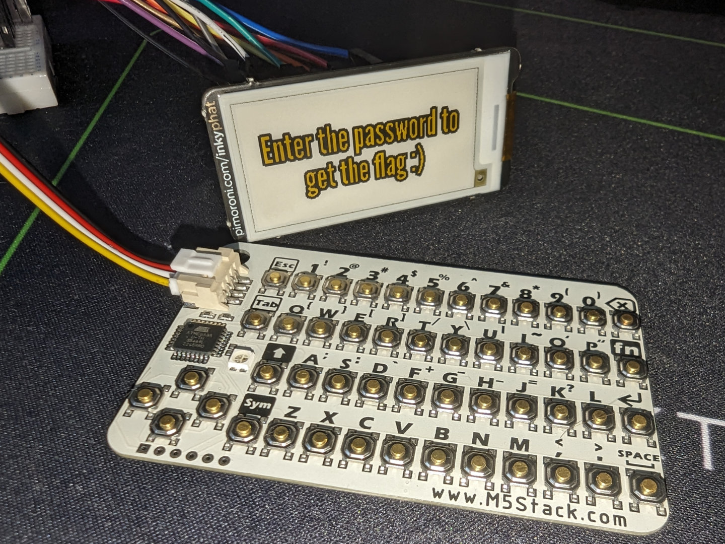 | ||
| 14 | |||
| 15 | 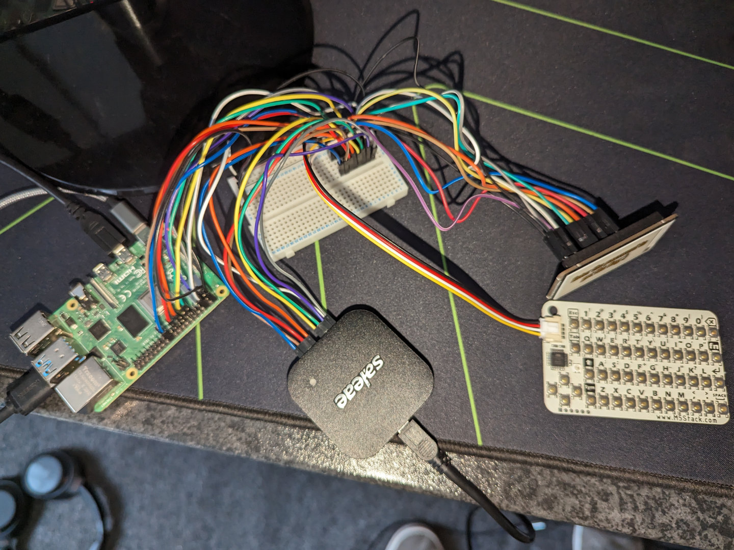 | ||
| 16 | |||
| 17 | 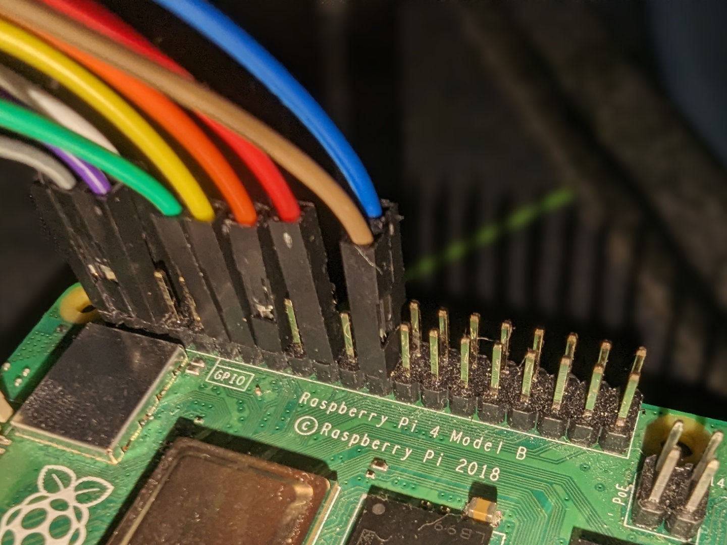 | ||
| 18 | |||
| 19 | 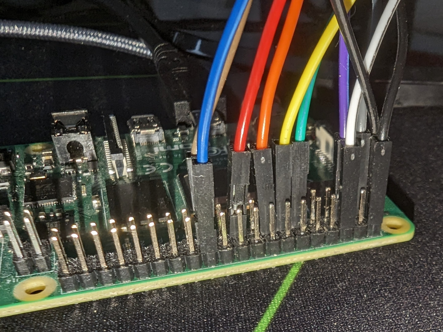 | ||
| 20 | |||
| 21 | 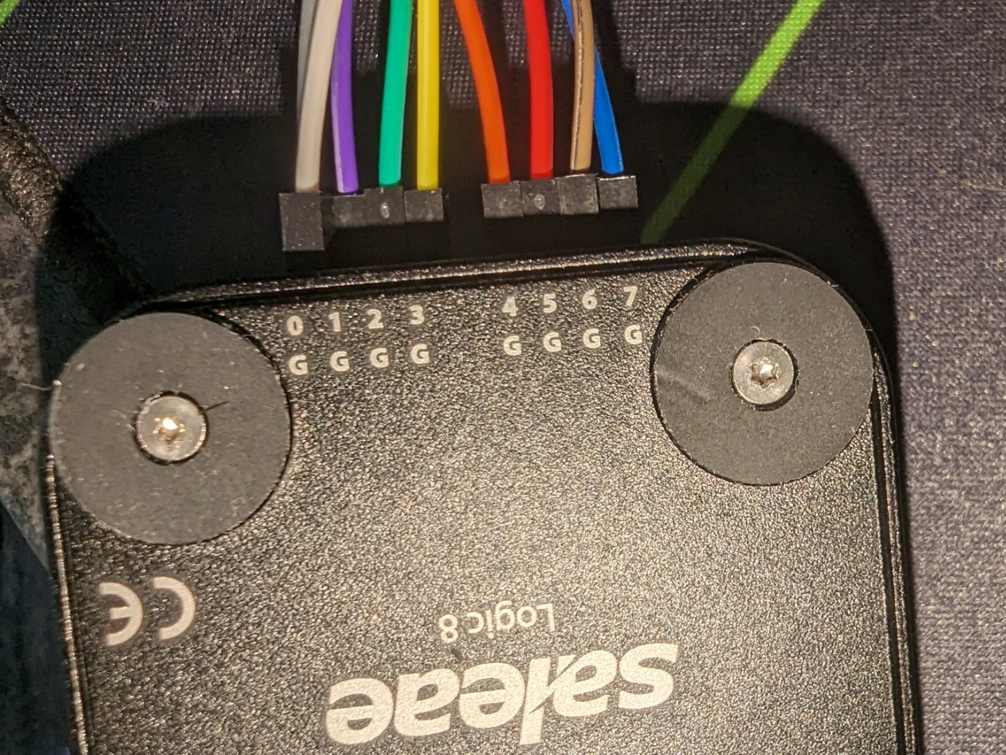 | ||
| 22 | |||
| 23 | 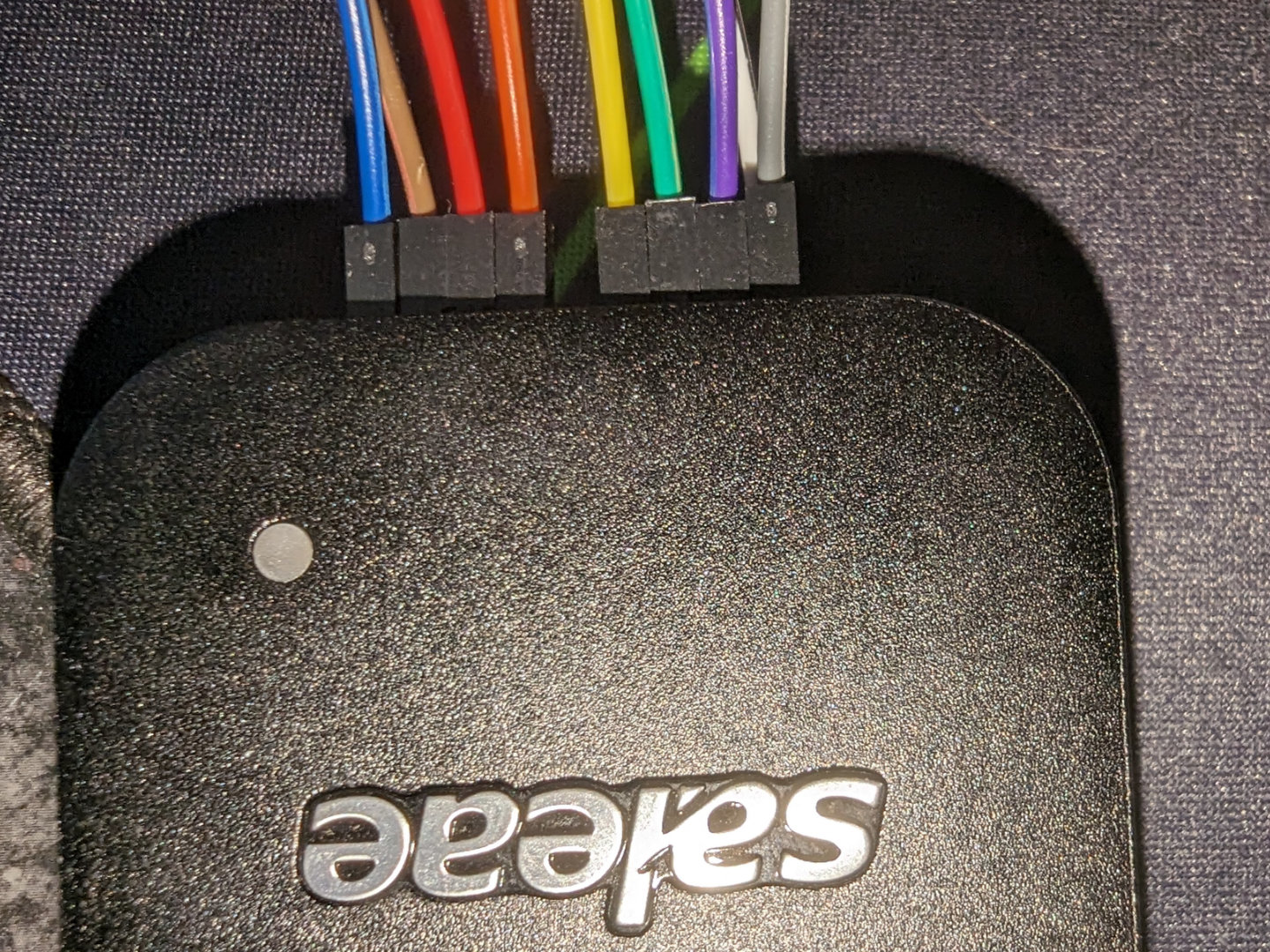 | ||
| 24 | |||
| 25 | 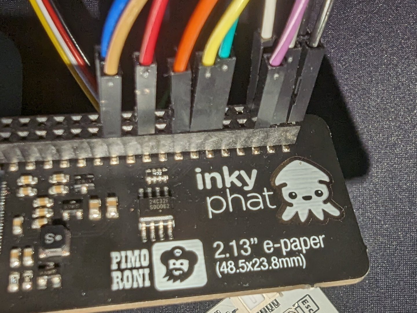 | ||
| 26 | |||
| 27 | 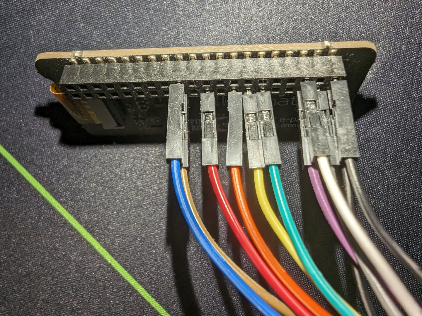 | ||
| 28 | |||
| 29 | ## Intro | ||
| 30 | Instead of sleeping, I made the mistake^Wwise decision of looking at my | ||
| 31 | Discord notification that said there was a hardware challenge in this CTF. It | ||
| 32 | just so happened that there it was using an ATmega-powered keyboard and an | ||
| 33 | e-paper screen, and it almost seemed like a coincidence since I was designing | ||
| 34 | my own keyboard and wanted to interface with an e-paper screen in the near | ||
| 35 | future. This seemed like a great learning opportunity so I started working on | ||
| 36 | the two-part challenge. | ||
| 37 | |||
| 38 | There were a few files inside the `dist.zip`, with the most | ||
| 39 | interesting one being capture.sal which was technically a zip but actually | ||
| 40 | the analyzer file for Salae. Sadly it seemed to need their proprietary | ||
| 41 | program to open. | ||
| 42 | |||
| 43 | 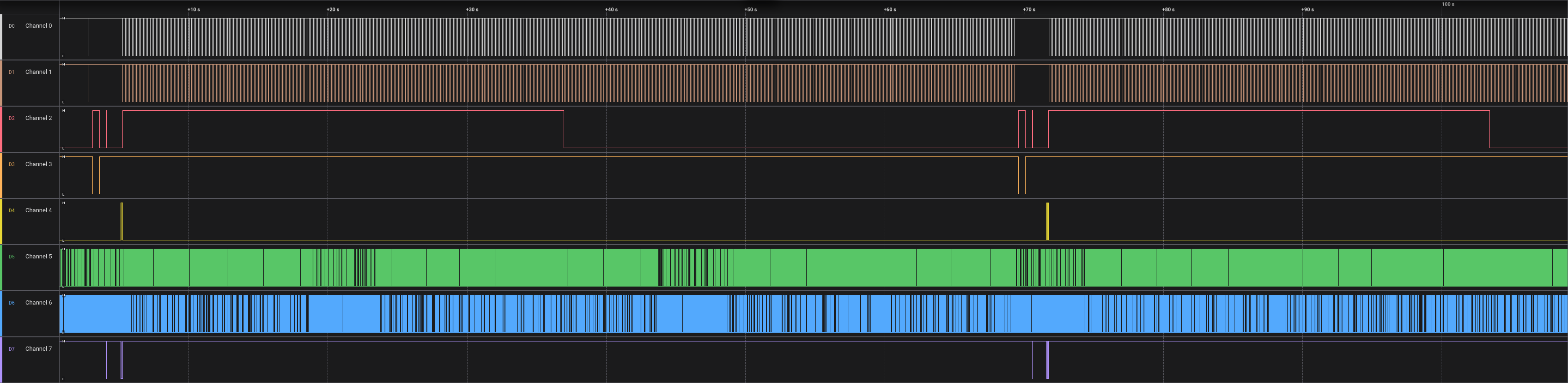 | ||
| 44 | |||
| 45 | The first thing I did was figuring out what each channel was connected to | ||
| 46 | and what it meant. It seemed that the keyboard and display were controlled by | ||
| 47 | the Raspberry Pi which then seemed to go to the logic analyzer. So I looked | ||
| 48 | at what each channel was connected to and based on its connected pin on the | ||
| 49 | Pi, I found its function via pinout.xyz. I ended up with this: | ||
| 50 | |||
| 51 | ``` | ||
| 52 | Channel 0: P03 I2C SDA | ||
| 53 | Channel 1: P05 I2C SCL | ||
| 54 | Channel 2: P11 GPIO 17 (busy) | ||
| 55 | Channel 3: P13 GPIO 27 (reset) | ||
| 56 | Channel 4: P15 GPIO 22 (data/command) | ||
| 57 | Channel 5: P21 MOSI | ||
| 58 | Channel 6: P23 SPI0 SCLK | ||
| 59 | Channel 7: P24 SPI0 CE0 | ||
| 60 | ``` | ||
| 61 | |||
| 62 | 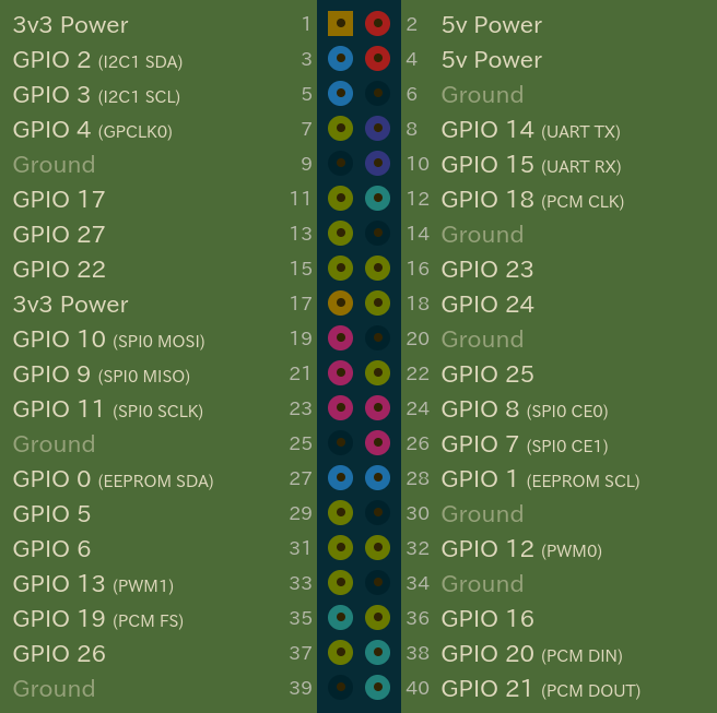 | ||
| 63 | |||
| 64 | ## Part 1 | ||
| 65 | In Logic 2, I opened the I2C analyzer and outputted the dump in the | ||
| 66 | terminal tab into a file | ||
| 67 | |||
| 68 | 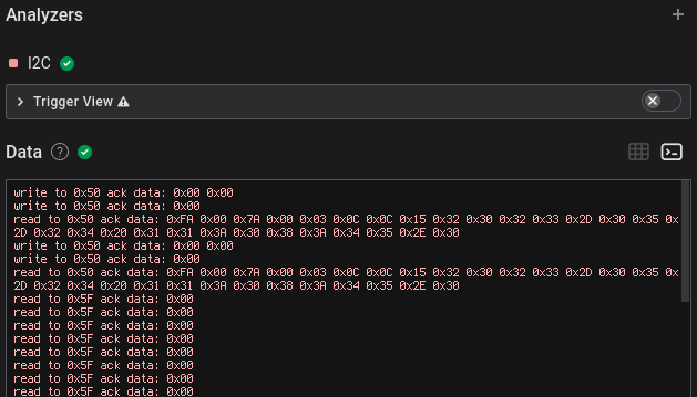 | ||
| 69 | 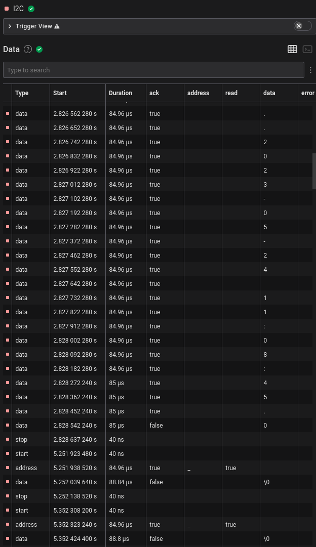 | ||
| 70 | It seemed there was a lot of NUL bytes being sent, probably indicating | ||
| 71 | that there wasn’t anything during that cycle, and a few seconds later there | ||
| 72 | were also some other different bytes with NUL and some `0x01` | ||
| 73 | bytes in between, and these seemed to be printable ASCII. | ||
| 74 | |||
| 75 | ``` | ||
| 76 | read to 0x5F ack data: 0x01 | ||
| 77 | read to 0x5F ack data: 0x01 | ||
| 78 | read to 0x5F ack data: 0x66 | ||
| 79 | read to 0x5F ack data: 0x6c | ||
| 80 | read to 0x5F ack data: 0x61 | ||
| 81 | read to 0x5F ack data: 0x67 | ||
| 82 | read to 0x5F ack data: 0x7b | ||
| 83 | read to 0x5F ack data: 0x37 | ||
| 84 | read to 0x5F ack data: 0x01 | ||
| 85 | read to 0x5F ack data: 0x31 | ||
| 86 | read to 0x5F ack data: 0x37 | ||
| 87 | read to 0x5F ack data: 0x66 | ||
| 88 | read to 0x5F ack data: 0x37 | ||
| 89 | read to 0x5F ack data: 0x35 | ||
| 90 | read to 0x5F ack data: 0x01 | ||
| 91 | read to 0x5F ack data: 0x33 | ||
| 92 | read to 0x5F ack data: 0x32 | ||
| 93 | read to 0x5F ack data: 0x7d | ||
| 94 | read to 0x5F ack data: 0x01 | ||
| 95 | read to 0x5F ack data: 0x0d | ||
| 96 | ``` | ||
| 97 | |||
| 98 | Filtering out the `0x00` and `0x01` data bytes and | ||
| 99 | converting to ASCII results in `flag{717f7532}`. | ||
| 100 | |||
| 101 | ## Part 2 | ||
| 102 | 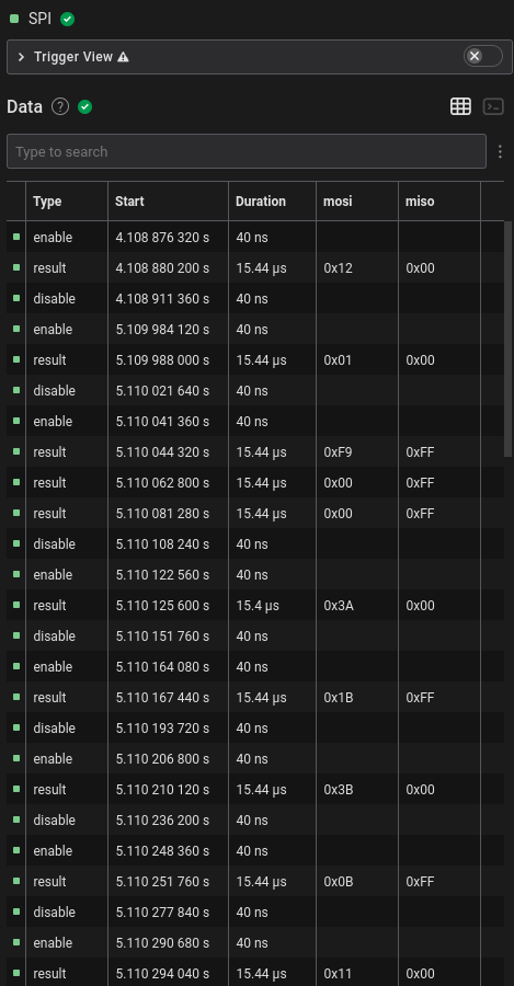 | ||
| 103 | |||
| 104 | I first outputted the SPI dump from the analyzer into a file and kept only | ||
| 105 | the `MOSI` and `MISO` columns. | ||
| 106 | |||
| 107 | ``` | ||
| 108 | Time [s],Packet ID,MOSI,MISO | ||
| 109 | 4.108880200000000,0,0x12,0x00 | ||
| 110 | 5.109988000000000,0,0x01,0x00 | ||
| 111 | 5.110044320000000,0,0xF9,0xFF | ||
| 112 | 5.110062800000000,0,0x00,0xFF | ||
| 113 | 5.110081280000000,0,0x00,0xFF | ||
| 114 | 5.110125600000000,0,0x3A,0x00 | ||
| 115 | 5.110167440000000,0,0x1B,0xFF | ||
| 116 | 5.110210120000000,0,0x3B,0x00 | ||
| 117 | 5.110251760000000,0,0x0B,0xFF | ||
| 118 | ``` | ||
| 119 | |||
| 120 | To actually understand what’s going on, I couldn’t find any proper | ||
| 121 | documentation initially. There wasn’t even a proper datasheet on DigiKey; the | ||
| 122 | “datasheet” was just a summary of the product. | ||
| 123 | |||
| 124 | 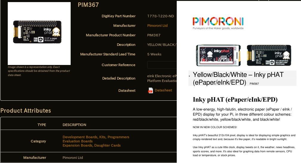 | ||
| 125 | |||
| 126 | Then I found the [Python library | ||
| 127 | source from Pimoroni](https://github.com/pimoroni/inky) of their epaper screens, which is probably what was | ||
| 128 | used to make this challenge. | ||
| 129 | |||
| 130 | ```python | ||
| 131 | def setup(self): | ||
| 132 | """Set up Inky GPIO and reset display.""" | ||
| 133 | if not self._gpio_setup: | ||
| 134 | if self._gpio is None: | ||
| 135 | try: | ||
| 136 | import RPi.GPIO as GPIO | ||
| 137 | self._gpio = GPIO | ||
| 138 | except ImportError: | ||
| 139 | raise ImportError('This library requires the RPi.GPIO module\nInstall with: sudo apt install python-rpi.gpio') | ||
| 140 | self._gpio.setmode(self._gpio.BCM) | ||
| 141 | self._gpio.setwarnings(False) | ||
| 142 | self._gpio.setup(self.dc_pin, self._gpio.OUT, initial=self._gpio.LOW, pull_up_down=self._gpio.PUD_OFF) | ||
| 143 | self._gpio.setup(self.reset_pin, self._gpio.OUT, initial=self._gpio.HIGH, pull_up_down=self._gpio.PUD_OFF) | ||
| 144 | self._gpio.setup(self.busy_pin, self._gpio.IN, pull_up_down=self._gpio.PUD_OFF) | ||
| 145 | |||
| 146 | if self._spi_bus is None: | ||
| 147 | import spidev | ||
| 148 | self._spi_bus = spidev.SpiDev() | ||
| 149 | |||
| 150 | self._spi_bus.open(0, self.cs_pin) | ||
| 151 | self._spi_bus.max_speed_hz = 488000 | ||
| 152 | |||
| 153 | self._gpio_setup = True | ||
| 154 | |||
| 155 | self._gpio.output(self.reset_pin, self._gpio.LOW) | ||
| 156 | time.sleep(0.5) | ||
| 157 | self._gpio.output(self.reset_pin, self._gpio.HIGH) | ||
| 158 | time.sleep(0.5) | ||
| 159 | |||
| 160 | self._send_command(0x12) # Soft Reset | ||
| 161 | time.sleep(1.0) | ||
| 162 | self._busy_wait() | ||
| 163 | |||
| 164 | def _update(self, buf_a, buf_b, busy_wait=True): | ||
| 165 | """Update display. | ||
| 166 | |||
| 167 | Dispatches display update to correct driver. | ||
| 168 | |||
| 169 | :param buf_a: Black/White pixels | ||
| 170 | :param buf_b: Yellow/Red pixels | ||
| 171 | |||
| 172 | """ | ||
| 173 | self.setup() | ||
| 174 | |||
| 175 | self._send_command(ssd1608.DRIVER_CONTROL, [self.rows - 1, (self.rows - 1) >> 8, 0x00]) | ||
| 176 | # Set dummy line period | ||
| 177 | self._send_command(ssd1608.WRITE_DUMMY, [0x1B]) | ||
| 178 | # Set Line Width | ||
| 179 | self._send_command(ssd1608.WRITE_GATELINE, [0x0B]) | ||
| 180 | # Data entry squence (scan direction leftward and downward) | ||
| 181 | self._send_command(ssd1608.DATA_MODE, [0x03]) | ||
| 182 | # Set ram X start and end position | ||
| 183 | xposBuf = [0x00, self.cols // 8 - 1] | ||
| 184 | self._send_command(ssd1608.SET_RAMXPOS, xposBuf) | ||
| 185 | # Set ram Y start and end position | ||
| 186 | yposBuf = [0x00, 0x00, (self.rows - 1) & 0xFF, (self.rows - 1) >> 8] | ||
| 187 | self._send_command(ssd1608.SET_RAMYPOS, yposBuf) | ||
| 188 | # VCOM Voltage | ||
| 189 | self._send_command(ssd1608.WRITE_VCOM, [0x70]) | ||
| 190 | # Write LUT DATA | ||
| 191 | self._send_command(ssd1608.WRITE_LUT, self._luts[self.lut]) | ||
| 192 | |||
| 193 | if self.border_colour == self.BLACK: | ||
| 194 | self._send_command(ssd1608.WRITE_BORDER, 0b00000000) | ||
| 195 | # GS Transition + Waveform 00 + GSA 0 + GSB 0 | ||
| 196 | elif self.border_colour == self.RED and self.colour == 'red': | ||
| 197 | self._send_command(ssd1608.WRITE_BORDER, 0b00000110) | ||
| 198 | # GS Transition + Waveform 01 + GSA 1 + GSB 0 | ||
| 199 | elif self.border_colour == self.YELLOW and self.colour == 'yellow': | ||
| 200 | self._send_command(ssd1608.WRITE_BORDER, 0b00001111) | ||
| 201 | # GS Transition + Waveform 11 + GSA 1 + GSB 1 | ||
| 202 | elif self.border_colour == self.WHITE: | ||
| 203 | self._send_command(ssd1608.WRITE_BORDER, 0b00000001) | ||
| 204 | # GS Transition + Waveform 00 + GSA 0 + GSB 1 | ||
| 205 | |||
| 206 | # Set RAM address to 0, 0 | ||
| 207 | self._send_command(ssd1608.SET_RAMXCOUNT, [0x00]) | ||
| 208 | self._send_command(ssd1608.SET_RAMYCOUNT, [0x00, 0x00]) | ||
| 209 | |||
| 210 | for data in ((ssd1608.WRITE_RAM, buf_a), (ssd1608.WRITE_ALTRAM, buf_b)): | ||
| 211 | cmd, buf = data | ||
| 212 | self._send_command(cmd, buf) | ||
| 213 | |||
| 214 | self._busy_wait() | ||
| 215 | self._send_command(ssd1608.MASTER_ACTIVATE) | ||
| 216 | ``` | ||
| 217 | |||
| 218 | It was also communicating over SPI which seemed to indicate that this was | ||
| 219 | the proper library. Then I looked at the `setup()` and | ||
| 220 | `_update()` functions in | ||
| 221 | `library/inky/inky_ssd1608.py`, and the SPI commands that were | ||
| 222 | sent in the analyzed dump log matched exactly, including each byte of the LUT | ||
| 223 | table. | ||
| 224 | |||
| 225 | All the SPI commands used in the library are used with named constants | ||
| 226 | that are defined `library/inky/ssd1608.py`: | ||
| 227 | |||
| 228 | ```python | ||
| 229 | """Constants for SSD1608 driver IC.""" | ||
| 230 | DRIVER_CONTROL = 0x01 | ||
| 231 | GATE_VOLTAGE = 0x03 | ||
| 232 | SOURCE_VOLTAGE = 0x04 | ||
| 233 | DISPLAY_CONTROL = 0x07 | ||
| 234 | NON_OVERLAP = 0x0B | ||
| 235 | BOOSTER_SOFT_START = 0x0C | ||
| 236 | GATE_SCAN_START = 0x0F | ||
| 237 | DEEP_SLEEP = 0x10 | ||
| 238 | DATA_MODE = 0x11 | ||
| 239 | SW_RESET = 0x12 | ||
| 240 | TEMP_WRITE = 0x1A | ||
| 241 | TEMP_READ = 0x1B | ||
| 242 | TEMP_CONTROL = 0x1C | ||
| 243 | TEMP_LOAD = 0x1D | ||
| 244 | MASTER_ACTIVATE = 0x20 | ||
| 245 | DISP_CTRL1 = 0x21 | ||
| 246 | DISP_CTRL2 = 0x22 | ||
| 247 | WRITE_RAM = 0x24 | ||
| 248 | WRITE_ALTRAM = 0x26 | ||
| 249 | READ_RAM = 0x25 | ||
| 250 | VCOM_SENSE = 0x28 | ||
| 251 | VCOM_DURATION = 0x29 | ||
| 252 | WRITE_VCOM = 0x2C | ||
| 253 | READ_OTP = 0x2D | ||
| 254 | WRITE_LUT = 0x32 | ||
| 255 | WRITE_DUMMY = 0x3A | ||
| 256 | WRITE_GATELINE = 0x3B | ||
| 257 | WRITE_BORDER = 0x3C | ||
| 258 | SET_RAMXPOS = 0x44 | ||
| 259 | SET_RAMYPOS = 0x45 | ||
| 260 | SET_RAMXCOUNT = 0x4E | ||
| 261 | SET_RAMYCOUNT = 0x4F | ||
| 262 | NOP = 0xFF | ||
| 263 | ``` | ||
| 264 | |||
| 265 | I then noticed that there was a long string of bytes being sent after a | ||
| 266 | `0x24` which in the library indicated that it was the memory | ||
| 267 | buffer for the black/white channel ending with a `0x00` | ||
| 268 | `MISO`, with the yellow/red channel afterward with a | ||
| 269 | `0x26` `MOSI` and also ended with `0x00` | ||
| 270 | `MISO` | ||
| 271 | |||
| 272 | ``` | ||
| 273 | ... | ||
| 274 | 0x19,0xFF | ||
| 275 | 0x01,0xFF | ||
| 276 | 0x00,0xFF | ||
| 277 | 0x3C,0x00 | ||
| 278 | 0x01,0xFF | ||
| 279 | 0x4E,0x00 | ||
| 280 | 0x00,0xFF | ||
| 281 | 0x4F,0x00 | ||
| 282 | 0x00,0xFF | ||
| 283 | 0x00,0xFF | ||
| 284 | 0x24,0x00 | ||
| 285 | 0xFF,0xFF | ||
| 286 | 0xFF,0xFF | ||
| 287 | 0xFF,0xFF | ||
| 288 | 0xFF,0xFF | ||
| 289 | 0xFF,0xFF | ||
| 290 | 0xFF,0xFF | ||
| 291 | 0xFF,0xFF | ||
| 292 | 0xFF,0xFF | ||
| 293 | 0xFF,0xFF | ||
| 294 | 0xFF,0xFF | ||
| 295 | ... | ||
| 296 | ``` | ||
| 297 | |||
| 298 | There also seemed to be two different updates at around 5 seconds and 70 | ||
| 299 | seconds. | ||
| 300 | |||
| 301 | 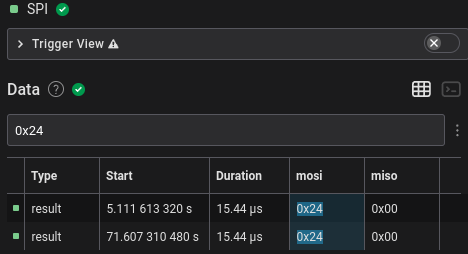 | ||
| 302 | |||
| 303 | However, the number of bytes written was 4250, which wasn’t the 3812.5 or | ||
| 304 | 2756 bytes I was expecting. This wasn’t divisible by 250 nor 122 and so I was | ||
| 305 | stuck for a long time. Looking through the library source for more than an | ||
| 306 | hour with my tired self didn’t help much either. As a last ditch attempt, I | ||
| 307 | tried converting the raw bytes into an image via Pillow, I used the | ||
| 308 | `L` mode (`8bpp`) and just got an uninteresting garbled | ||
| 309 | image. | ||
| 310 | |||
| 311 |  | ||
| 312 | |||
| 313 | ## Part 2 Part 2: Electric Boogaloo | ||
| 314 | 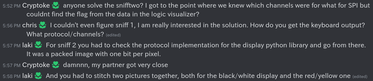 | ||
| 315 | 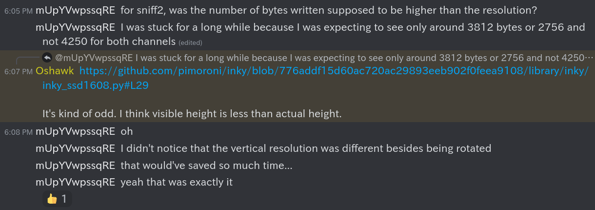 | ||
| 316 | |||
| 317 | After waking up and working on the CTF after it ended, my partner asked on | ||
| 318 | the Discord and found some interesting very helpful information. It turned | ||
| 319 | out the image was a packed 1bpp image. This meant that each byte in the | ||
| 320 | memory framebuffer contained 8 pixels (8 bits / 1 bits per pixel = 8 | ||
| 321 | pixels). | ||
| 322 | |||
| 323 | ```python | ||
| 324 | # under show() | ||
| 325 | buf_a = numpy.packbits(numpy.where(region == BLACK, 0, 1)).tolist() | ||
| 326 | buf_b = numpy.packbits(numpy.where(region == RED, 1, 0)).tolist() | ||
| 327 | ``` | ||
| 328 | |||
| 329 | In the Python source, this was shown by `buf_a` and | ||
| 330 | `buf_b` being packed bits of 1bpp via NumPy. I don’t know much | ||
| 331 | about NumPy, so this was a skill issue as I initially assumed it was a | ||
| 332 | complicated way of saving all the black and red pixels into lists. This is a | ||
| 333 | good reminder that the documentation should be checked for all unfamiliar | ||
| 334 | functions instead of naively assuming what they seem to do. | ||
| 335 | |||
| 336 | Also in addition to the screen being rotated by 90 degrees, the vertical | ||
| 337 | resolution is actually 136 pixels and not 120 according to the driver. | ||
| 338 | |||
| 339 | Knowing all this solved all my problems as 4250 * 8 was indeed divisible | ||
| 340 | by 250 and the actual vertical resolution 136. | ||
| 341 | |||
| 342 | All I had to do was change the Pillow mode when converting the bytes to an | ||
| 343 | image from `L` (8bpp) to `1` (1bpp) and the (rotated) | ||
| 344 | resolution from `(250, 16)` to `(136, 250)` and got an | ||
| 345 | actual image. | ||
| 346 | |||
| 347 | 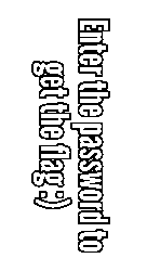 | ||
| 348 | |||
| 349 | I used the first updated bytes which was the screen shown in the | ||
| 350 | challenge’s screenshots. Using the second update’s bytes gave half of the | ||
| 351 | flag in the black/white channel and the other half in the yellow/red | ||
| 352 | channel. | ||
| 353 | |||
| 354 | 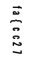 | ||
| 355 | 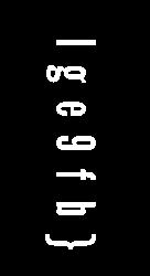 | ||
| 356 | |||
| 357 | Each character index in both channels seemed to alternate, so the actual | ||
| 358 | flag was `flag{ec9cf2b7}`. After I finished writing this writeup | ||
| 359 | and seeing the two images side-by-side, they probably could’ve been overlayed | ||
| 360 | after one’s colours are inverted, and is probably what was meant by | ||
| 361 | “stitching” the channels together. | ||
| 362 | |||
| 363 | ## Conclusion | ||
| 364 | This was my most favourite CTF challenge by far and I learned a lot, | ||
| 365 | especially about stuff I wanted to learn like how SPI e-paper screens work | ||
| 366 | and not be lost with I2C. I am personally now curious whether the SPI screens | ||
| 367 | can be interfaced directly with the MCU instead of going through an | ||
| 368 | intermediate daughterboard/HAT and how different the protocol for parallel | ||
| 369 | screens are since they’re much faster and use more pins. | ||